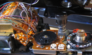
Canon A-1 Mode Switch Repair

My Canon A-1 (which I fixed the wheeze on here but please don’t use that method because it’s a bad hack that could cause more harm than good) was doing something weird. Every so often, when taking a photo indoors in aperture priority mode (Av), I would notice that the camera’s settings would jump to a really long exposure time like 30 seconds. Sometimes the only notice I’d get of this would be the camera actually taking a 30 second exposure instead of the more normal 1/60th at f/1.4 that I was hoping for.

The A-1 uses a single dial to select aperture settings in Av mode and shutter settings in Tv mode. The mode switch changes which part of the dial is displayed – the outer ring for shutter speeds, and the inner ring for apertures. At some point, I realised that the erroneous shutter speeds I was getting in Av mode were the shutter speeds at the same dial position in Tv mode. This was most noticeable when it was at the f/1.4 and 30 second position, but way less obvious when it was at the f/4 and 1/2 second position, because the difference between the expected and actual shutter speeds was smaller. I think this has been the cause of a few blurry photos. So I opened the camera to investigate.

The mode switch rotates around the shutter button, but it moves a sliding plate that has a crescent-shaped part that hides the unnecessary side of the dial, with a line half way along it to indicate the current setting. On the underside of one corner, this plate has a pair of brushes which bridge two contacts on the circuit board below when in Av mode and leave them open when in Tv mode. This plate is mounted on another plate which is only really fixed along the front side of the camera, the side opposite the brushes. This means that the contact of the brushes is slightly susceptible to flex due to finger pressure on the top of the camera, such as when finding and using the shutter button by touch, switching modes, or moving the dial.

Canon A-1 mode switch repair
Location of contacts, brushes, and crescent indicator on the sliding plate moved by the mode switch
Canon A-1 mode switch repair
Brushes from the underside. Note the two screw holes on the opposide side of the plate to the brushes.
Canon A-1 mode switch repair
The contacts bridged by the brushes. Note the tracks worn on the PCB from when the brushes slide back off the contacts when entering Tv mode.

I took the plate off and cleaned the circuit board contacts with some isopropyl alcohol. I also bent the brushes on the underside of the plate slightly downwards for a little extra spring pressure on the contacts, to hopefully reduce the effect of flex. Then I put it all back together. (Aside: my camera is missing a few washers from the shutter button and winder mechanisms, as well as the detent ball for the setting dial guard —  I think someone has been in here before me.)

So far, so good. I haven’t noticed the shutter speed bouncing around, and the test roll photos turned out fine.

Canon A-1 test
Canon A-1 test photo on Kodak UltraMax 400
Canon A-1 test
Canon A-1 test photo on Kodak UltraMax 400
Canon A-1 test
Canon A-1 test photo on Kodak UltraMax 400

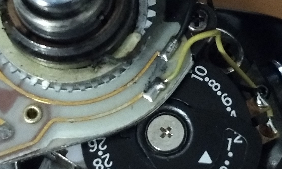
Nikon FG Early Activation Hack

While I was working on the light meter for the Nikon FG, I thought of a ‘fix’ that I’d read about for another issue – making the light meter active as soon as the film door is closed. The FG, by default, will only activate its light meter after the film counter is on 1. If you’re like me, you want to get as many frames out of your film as possible, so activating the camera’s light meter as soon as you’ve put in a new film is useful.

The fix for this that I had read about is to solder a piece of wire between the contacts that detect the position of the frame counter. However, that requires soldering. I’ve moved recently and my soldering iron is in a box somewhere. Can’t be bothered with all that.

A memory surfaced, back from the depths of time, about an overclocking hack for the first generation of Intel Celeron computer processors. As I recall, these processors were protected from overclocking. However, you could bypass this protection by drawing a line between two exposed electronic components on the processor chip with a lead pencil. With this conductive line in place, you could modify some of the processor settings and get moar speeds.

So…

Nikon FG light meter adjustment
Hacky hacky hacky

You can see, on the right, two points of solder that connect the contacts to the black and yellow wires. The sources I’ve seen suggested soldering a small piece of wire between these two. You could also do the same where the black and yellow wires are soldered to the PCB. But I drew a fairly liberal line of 3B pencil lead between the contacts on the PCB, which you can just see as a smudgy grey line. It works. The meter is now active as soon as the film door is closed.

And, if I ever want to revert it to normal behaviour, all I’ll need is an eraser.

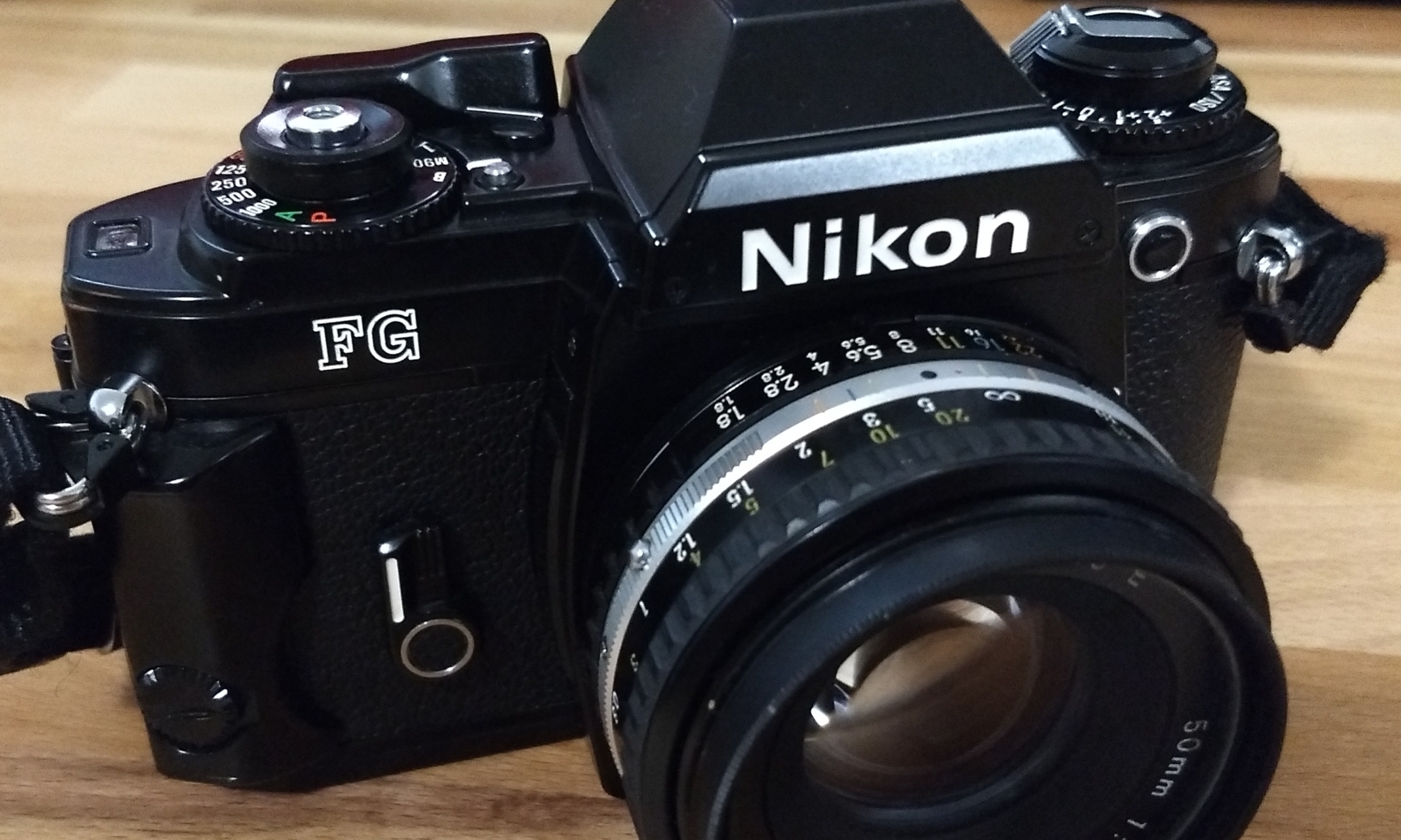
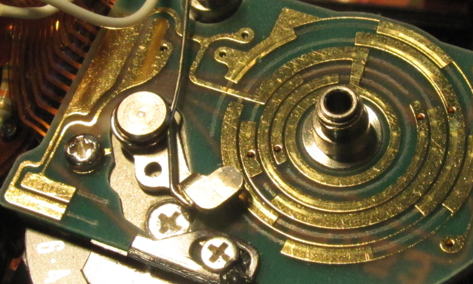
Nikon FG Light Meter Alignment

When I acquired an old family friend’s photographic enlargers a couple of years ago, they threw in a bag of other gear. In the bag was a Nikon F4 (still haven’t got it working – one day!) and a couple of lenses: a Series E 100mm and a Nikkor-H 85mm f/1.8. Too much fine glass to leave languishing in a bag. But as a Canon boy from way back, I didn’t have a (working) Nikon to put them to use.

Nikon FG light meter adjustment
Cue impulse buy

I bought a Nikon FG from Kamerastore with a very dim, basically unusable light meter, which dropped its price to about half of what a working model would go for. I figured I could probably do something about that, and that even if not, external light meters are a thing. When I got it, the light meter was indeed very dim, though by moving my eye around the viewfinder I could see that the amount of light would change. This made me suspect that it was an alignment issue rather than bad LEDs or anything else electronic.

The top plate comes off fairly easily, as long as you have a decent small diameter spanner wrench. The best one I’ve found so far is a 100mm divider from a builder’s shop. The points are a bit thick, but it’s basic steel and I can file them down if it becomes necessary.

Nikon FG light meter adjustment
Pointy and stable

The LEDs are on the end of a flex circuit to the left of the prism (with the lens mount away from you). The flex has a connector that is used to adjust how far down the slot between the prism and the body the flex reaches. This essentially adjusts how well aligned the LEDs align with a mask somewhere in that gap that provides the circular shape of the meter LEDs and the arrows of the over- and under-exposure indicators.

The connector has a central screw to fix it in place. There are two screws on either side of the central screw that align the connector once the central screw is loosened or removed. Both adjust the depth of the connector; adjusting to different depths can adjust slightly in the front-to-back axis. These adjustment screws have flanges that sit below the connector, so the connector is sandwiched between the adjustment screws and the central screw (which makes it important not to over-tighten the central screw – according to the repair article I used, this can bend the connector).

Nikon FG light meter adjustment
Before: the larger black screw right in the centre of the picture secures the connector, while the two silver screws beside it adjust the connector’s height

After some trial and error, trying to find the best way to adjust the screws, I turned them all the way down, and the LEDs were definitely improved but still not fully clear – the circles were a bit dim on one side, indicating alignment was still not perfect. I was going in the right direction, but not far enough. The flanges on the adjustment screws are relatively thick, so there was extra room to move downwards if the flanges weren’t a factor. I removed the adjustment screws entirely and just fixed the connector all the way down, but this was too far – much worse. The flanges were too thick but something was still required. I made a spacer out of some film, cutting holes for all three screws, but this was too thin. I then made one from a piece of card that was about half the thickness of the flange, and this produced a nearly perfect alignment.

Nikon FG light meter adjustment
After: the piece of card fits below the connector, which is now secured with all three screws

I suspect this alignment hack was required because something else in the camera is out of alignment – perhaps it’s had a bump at some point in its history. But I’m not too concerned. The light meter is now quite usable – it’s better out of full sun, but it’s usable in daytime and that’s a huge improvement. And I’m really enjoying this camera. Light meter aside (give me a match needle any day) and ignoring the abrupt jolt at the end of the film wind action, it’s a fun and capable little machine. And I do mean little – the smallest and lightest SLR I have by a decent margin. I bought a Series E 50mm f/1.8 to use with it based on some pretty good reviews of this lens (because 50mm is my jam) and the photos from the test roll are clear and pleasant.

Nikon FG test roll

Nikon FG test roll

I’m pretty happy with how this turned out. I know that it’s not the most elegant repair, perhaps not even the most effective, but the camera is far more usable now and that’s what counts. I’ve rescued a camera that was on the verge of the parts bin, in order to make use of photography gear that was going unused, and I think that’s what this whole camera repair thing is all about. For me, at least.

Minolta X-9 Top Plate Removal and Reassembly

I posted these instructions over on Photrio, but thought I’d post them here as well.

In my last post, I replaced a dud capacitor on a Minolta X-9 that I was given by a friend. The Minolta X-9, otherwise known as the X-300s I believe, is similar to the X-300 and other X-series cameras, but not exactly the same. I couldn’t find specific instructions for working on this camera anywhere. Removing the bottom plate to fix the capacitor is easy, and the X-300 repair manual suffices for many other things, but the top plate is slightly different to the other X-series cameras, so I thought I’d figure out the way to remove it and put it here so others can use it. I mean, it’s really only points 1 and 2 that are different, but sometimes it helps to know things specifically. And I’m starting to think this camera is a bit underrated, once you come to terms with all the plastic.

Sorry for all the dirt in the photos, by the way.

Unless otherwise specified, all screws need a size J000 JIS screwdriver. All screws unscrew anticlockwise like normal.

Removal

1. Remove the finger plate around the shutter button. Prize this up from the front, gently, with a thin plastic tool. You can run this around the edges, but you get more purchase near the shutter button on both sides as there’s a locator pin further down. Just don’t apply too much pressure to the bit that goes around the shutter button because it’s thin.

Minolta X-9 / X-300s top plate removal

Minolta X-9 / X-300s top plate removal

2. There are two screws below the finger plate, marked in yellow. Undo these and you can remove the cover over the shutter speed selection dial and film advance lever screw. (The red arrow is the hole the locator pin goes into.)

Minolta X-9 / X-300s top plate removal

3. Remove the film advance lever screw (red arrow). This needs a size J1 screwdriver.

Minolta X-9 / X-300s top plate removal

4. When you take off the film advance lever, take care about the spring beneath it. This is tricky to get back in – it needs about a 270 degree anticlockwise rotation from its resting state to line up correctly, and you’ll probably need three hands. One end goes into the hole on the edge of the advance lever, the other goes into the hole marked in the second photo.

Minolta X-9 / X-300s top plate removal

Minolta X-9 / X-300s top plate removal

5. Undo the nut around the film advance axle with a spanner wrench.

Minolta X-9 / X-300s top plate removal

6. Take off the obvious top plate screws: two on either side of the viewfinder, one on the left end, and two on the name plate on the front.

Minolta X-9 / X-300s top plate removal

Minolta X-9 / X-300s top plate removal

Minolta X-9 / X-300s top plate removal

7. Take note of the position of your ISO selector and power switch. Undo the screw on the rewind knob. This needs a size J0 screwdriver, and you’ll need to brace the other end of the rewind axle with a cloth-covered screwdriver or similar. Lift off the rewind knob.

Minolta X-9 / X-300s top plate removal

8. Undo the plastic disk with a spanner wrench. This holds the ISO selector wheel in place. There is a circular wave spring below it. Lift off the ISO selector wheel

Minolta X-9 / X-300s top plate removal

Minolta X-9 / X-300s top plate removal

9. You can now take off the top plate. Don’t be too eager, because there are three wires leading to the hot shoe that are soldered on. Desolder them if you need to remove the top plate completely.

Minolta X-9 / X-300s top plate removal

So that’s the top plate removed.

Reassembly

A few pointers on lining things up when reassembling:

– The shutter button has a central pole that goes into a light grey tube near the shutter speed dial. The spring goes on first. There are three tabs around the edge of the button that prevent it from fitting through the top plate, so make sure you put this back before the top plate goes on.

Minolta X-9 / X-300s top plate removal

Minolta X-9 / X-300s top plate removal

– The viewfinder surround is only held in by the top plate screws on either side of it. There are two channels around its edge – the outermost is for attaching an eyecup or some such, and the innermost sits into the top plate. When sitting correctly in the top plate, the tabs with the screw holes fit between the top plate and the camera body. You might need some extra arms to keep this in place while also lining up the shutter button and power switch when you’re putting the top plate back on.

Minolta X-9 / X-300s top plate removal

Minolta X-9 / X-300s top plate removal

– The power switch actuator is the white lever near the rewind pole. The power switch interfaces with the U-shaped indentation at the end of the lever. (The ISO interface pole is behind the axle – just ignore that arrow.)

Minolta X-9 / X-300s top plate removal

– When the top plate is back on, but before you replace the ISO selector wheel, you can tell if the power switch is interfacing properly by viewing the switch through a hole in the top plate.

Switch set to Off: all white (lever is directly below the hole)

Minolta X-9 / X-300s top plate removal

Switch set to On: half white half empty (looking at the edge of the lever through the hole)

Minolta X-9 / X-300s top plate removal

– The ISO selector wheel has a hole on its underside that interfaces with the grey pole you can see at the far left of the two pictures above.

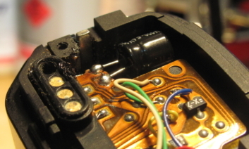
Minolta X-9 Capacitor Replacement

Last year I bought three enlargers from a family friend, who also threw in a bag of other camera stuff. This included a Nikon F4 and a Minolta X-9, neither of which worked properly. The F4 is my dream fix, but it’s a complicated beast. The X-9 (also called/very similar to the X-300S or X-370N) is a simpler machine by anyone’s estimation. Judging by resale prices, it’s considered outright basic. I am getting the impression, though, that it can easily outperform expectations as long as you can look past its gloriously 1980s plastic shell.

Minolta X-9 capacitor repair
The Minolta X-9 in question. The sorry-looking lens is a project for another day.

According to the internet, many of the later Minolta X series cameras are prone to a capacitor failure. An affected camera will appear to work until the shutter button is fully depressed, at which point the camera will power down; because the shutter never releases, the film advance lever can seem stuck. This Minolta X-9 displayed exactly this issue – the light meter would work on a half-press of the shutter button, but then the camera would die as soon as I pressed further.

I opened the bottom of the camera to have a look. Not without difficulty – I stripped the head of the screw nearest the capacitor in question. It was very stiff and I suspect it was slightly corroded by the residue from the burst capacitor, traces of which could be seen on the underside of the base plate. The plastic at the base of the capacitor, between the pins, was protruding further than it should, indicating that it had burst through the bottom and towards the screw.

Minolta X-9 capacitor repair
The old capacitor in place. It had burst out the bottom towards its pins, and you could see some residue nearby.

The most difficult part of this repair, for me, was learning to solder and desolder. This is a skill that I have come to learn is essential for repairing cameras – almost any camera made after 1970 seems to have parts that can only be removed after certain wires are desoldered (even the Voigtländer Bessamatic, which is a chaotic mechanical masterpiece). Thankfully, there is an electronics retailer in Australia that still provides an abundance of educational materials and affordable supplies for learning to solder. I learned the basics by making a small device with two flashing LEDs. This was a bit challenging, as I had decided to use lead-free solder for safety reasons, and my soldering iron tip was old and corroded; things got easier when I replaced the tip, and I was able to complete the device. Then I tried to unsolder it, found this difficult and gave up, and put it back together. As it still worked, I figured this was a good enough start…

Heady with my success, I dived straight into replacing the capacitor on the Minolta X-9. The old capacitor came off easily enough, so I trimmed and bent the pins of the new capacitor (took a while to find replacements with the same specifications and dimensions, but it is possible) and forged ahead. It’s a bit tricky to get the right alignment, since there’s not much support for the capacitor and you’re soldering it to a flexible circuit. I screwed up the alignment at first and had to re-solder it, and given the higher melting point of lead-free solder I was pretty afraid that I’d cooked something. Doubly so, when I put some batteries into the camera and nothing worked at all.

Minolta X-9 capacitor repair
The new capacitor soldered in. Those huge globs of solder are proof that I had only learned to solder recently and opted for the “overkill” approach.

I checked continuity between the capacitor pins and the next components on the flex circuit, and that was all fine. I measured voltage at the flex circuit and it checked out at around 3V, as it should have. But the camera wouldn’t even turn on. I was certain I’d killed it. And it’s not even a nice-looking paperweight.

When nothing works, go back to basics.

To test the camera, I had been using batteries straight out of my Minolta XE-5. These batteries were powering that camera’s light meter just fine, and they were measuring in at the correct voltage, so I assumed they were ok. But then, just in case, I put in a fresh pair of batteries. I pressed the shutter button. It fired. I pushed the film advance lever. It moved. I did it again. And again. And again.

Now, I know this is a basic camera, a manual focus SLR released at the time Minolta was well into its autofocus phase. It has only two or three more functions than the XE-5, which is about 15 years older. And it looks very much like an SLR and Darth Vader’s suit were spliced in a teleporter incident. However, it’s the first camera that I have resurrected from a state of complete malfunction. I’m pretty pleased with that. And in the process, I’ve seen some indications that the functions it does have are well implemented. When I ran a test roll of film through, it was comfortably familiar to shoot with, and it was plastic enough that I didn’t feel compelled to treat it like porcelain, so I quite enjoyed the experience. I might post a review up here sometime.

Minolta XE-5 Film Advance Repair

A couple of months ago, just before the birth of my son, I fixed the film advance on my Minolta XE-5. The lever had not been completing its action properly, and when it got to the end of its rotation there would still be some film winding left to do, so it would just return loosely. It had to be pushed to the end of its travel again before the action would complete, the lever would return under spring action, and the shutter would be unlocked.

The XE-5’s plastic prism cover, though potentially more fragile than metal and (in my opinion) a slightly questionable aesthetic design choice, has the benefit of separating the top plate into three sections: the prism cover, and left and right covers made of metal. This simplifies some repairs, because if you only have to make a repair on one side, you don’t have to disassemble the other.

Minolta XE-5 winder return fix

Minolta XE-5 winder return fix

There’s not too much complicated about the top plate removal beyond making note of where things were aligned. I had the shutter speed dial set to Auto just as a reference (and to keep the dial from being moved), and I left the power selector set to On so that the shutter could be released while disassembled (for testing the winding function). Also important to align correctly is the strangely shaped part below the brass spring in the photo below, which interfaces between the film advance lever and its axle. The easy way to remember its alignment is tho make sure the larger, stronger tongue is on the left, as this is the part that transmits the lever’s force in an anticlockwise rotation.

Minolta XE-5 winder return fix

Once the top right cover is removed, you can just access the rachet that governs disengagement of the film advance lever, which needs to be cleaned to remove the gunk causing the issue. The ratchet is connected to the small brass pin that is between the two arms of a spring – in the photo below, this is below the PCB (gotta love those 1970s electronics!) and just to the right of the silver screw near the strap lug. You can tell that this is gunked up by moving the pin – it may be stiff.

Minolta XE-5 winder return fix

I cleaned the ratchet’s pivot and the end of the ratchet itself (where it engages the toothed plate connected to the film advance axle) with some isopropyl alcohol on the end of a toothpick that I’d whittled to a point, just dabbing on a small drop and waiting for it to dissolve the gunk and evaporate. I then applied a small amount of light synthetic oil to both areas. I could immediately feel that the ratchet moved more smoothly and quickly. I put the strangely shaped part and the advance lever back on top of the film advance axle temporarily and went through the fire-wind sequence a few times to check the repair was effective – the advance lever returned at the end of each stroke as it should, with no extra push necessary.

This camera has the smoothest film advance mechanism I have ever felt. It takes even less effort than a Voigtländer Vito C-series film advance, despite having a much more complicated shutter to charge. In fact, now that it’s fixed, it feels more broken – it is so smooth that it’s difficult to believe it’s working. I am a little bit in awe.

Voigtlander Vito CLR – Parts Bin Restoration Part 2

Restoring a camera is a twofold operation. You can restore a camera’s function, get it taking photos reliably, make it work the way it should (or as close as possible to how it should). But you can also restore a camera’s appearance, make it look the way it should. On some level, I’m less concerned with the aesthetics of a camera, as long as it doesn’t have a flow-on effect on function. I’d much rather have a working camera that looks a bit scrappy than a shiny camera that can’t take photos. However, if you want to finish the restoration completely, you need to address both aspects.

With this (quite obvious) dichotomy in mind, I followed up my recent work on the shutter of my parts bin Voigtländer Vito CLR with some work on the top cover of the camera, and specifically the control window for the exposure meter (to use the user manual’s terminology). The control window was separated from the cop cover and sitting loose in its hole. A few of the pictures on the internet of Vito CLRs that have the front-to-back oriented light meter show a similar state of affairs, so I think this must be a relatively common occurrence. Looking at the removed window and the underside of the top cover, I’m not surprised – the adhesive is rock-hard and looks quite a lot like rust. I’m a bit confused about how it would have originally been attached; it looks as though the adhesive went part of the way up the angled side of the window, but the hole in the top cover is large enough that this should not have been necessary. Given the state of the adhesive and the pictures of other examples, I’d be surprised if there was an example out there with the window intact in its original position (i.e. not restored), so I may never know.

Voigtländer Vito CLR light meter control window repair

The adhesive was quite stubborn – in fact, it wasn’t until it started dissolving ever so slightly in acetone (nail polish remover) that I realised it definitely wasn’t rust (isopropyl alcohol and naphtha didn’t cut it). The picture below shows how much (or how little) I was able to remove after soaking a tissue in nail polish remover and letting it sit in contact with the adhesive for around 5 minutes, then repeating.

Voigtländer Vito CLR light meter control window repair

To readhere the window to the top cover, I used some pieces of double-sided tape from a craft store. It’s not particularly heavy duty tape, but it’s nevertheless surprisingly tenacious stuff (it stuck to the semi-smoothed remnants of adhesive just fine, as to the mostly cleaned window) and it’s super easy to trim excess away with a craft scalpel. This shows where the tape went (with backing paper still in place; the piece on the right was trimmed down after the window was in place.

Voigtländer Vito CLR light meter control window repair

Initially, I readhered the window without addressing its paint. I think the paint is to add diffuse light to the light meter chamber. The meter (that is, the silhouette of the meter needle and the match needle) is reflected along the length of the camera below the rangefinder and then out through the base of the viewfinder, so I’m guessing (please chime in to correct me if I’m wrong) that the diffuse light helps to provide a more stable reflection in changing light conditions. The meter was quite visible in its current state, and I didn’t have any suitable paint, so I didn’t bother to address this at the time. I did, however, take the opportunity to clean all the viewfinder and rangefinder glass while the top cover was off.

Voigtländer Vito CLR light meter control window repair

Over the next day or so of thinking it over, I eventually realised I wasn’t really happy to leave the job half done. After all, the whole point of this part of the restoration was aesthetic; the meter already worked with its loose window, so why leave the appearance only half addressed? So I bought a paint pen from an office supplies store that was specifically for use on non-porous surfaces. I masked off the top of the meter with some scotch tape and painted the non-angled sides as a test. Getting an even coat was a little challenging at the edges, but it dried on well enough and with two coats it looked reasonably smooth. However, I hit a snag when trying to mask off the curved side of the top of the window – I had thought I could run the craft scalpel around the curved top to get the scotch tape to match the curve, but this proved too difficult. So I didn’t bother. The top of the curved side has a slight lip, and this was enough of a guide for the pen. Again, two coats and it was just about smooth enough, and the lightest of scrapes around the top edges with the scalpel neatened the edges well. I was a little concerned the two coats might be too thick to let much light through, but it’s fairly thin paint and is still translucent. And, when reattached, the window now looks much tidier. I’m not sure how close it looks to the original (it is very white), but it doesn’t look like a stained, half-gone mess anymore.

Voigtländer Vito CLR light meter control window repair

Voigtländer Vito CLR light meter control window repair

When I picked up the camera after first reattaching the window, it felt more solid, more complete. It was like the camera was itself again and knew it. Maybe I was going a bit loopy on acetone fumes but it was a rather satisfying moment. This camera wasn’t in a terrible condition when I bought it from the parts bin (if it had been, I probably wouldn’t have bought it), and these cameras aren’t especially rare or sought-after, but it is a capable little camera that can hold its own in terms of both functionality and image quality, and it needed some attention. I hope that it enjoys its second chance at life, now that it is hale and whole.

Voigtländer Vito CLR

Well, nearly whole. The loop of leatherette around the base of its lens barrel is still missing. But this is Australia. Dressing down is a national pastime.

Voigtlander Vito CLR – Parts Bin Restoration Part 1

Judging by the bulk of my recent camera acquisitions, I have a thing for trying to restore and recover the unloved. This started a while ago, I believe, with my Dad’s old Voigtländer Vito CD. It is clearly broken, and its shutter is gummed up to the point it doesn’t open willingly. I have a theory (one I’m unable to confirm, though production dates for these cameras support it) that Dad dropped the Vito CD and tried unsuccessfully to repair it; he then replaced it with a Vitoret R but wasn’t happy with its lack of a light meter, and so bought the Canon FT QL that is now the heart and soul of my photographic adventures. About 8 years ago I managed to work the Vito CD’s shutter free, but not permanently. I also bought a Zenit E with a broken shutter about that time, which is still in a hundred pieces in a box, so it hasn’t been all smooth sailing for the cameras I try to restore. But the Vito CD has stuck in my mind as something I have to finish one day.

With that in mind, I bought a Voigtländer Vito CLR from a parts bin at a camera fair. I asked what was wrong with it and the seller didn’t give a definite answer. The shutter speed ring was quite stiff, and the light meter window was loose, but the rangefinder appeared functional and the body was in fairly good condition. For $10 it would make a good parts camera, or a bargain of a baby rangefinder if I could get it working. As the top model of the Vito range, it has both a lightmeter like the Vito CD and a rangefinder like Dad’s old Vitoret R; it also has the Color-Skopar 50mm f/2.8 lens that is reputed to be a fair bit better than the Color-Lanthar lenses of the other two. It wasn’t a hard decision to buy it. And when it became evident that most of my other repair projects require (de)soldering work, I decided to take on the shutter speed ring repair, suspecting that there might be some misaligned or broken parts inside.

Voigtländer Vito CLR shutter

It’s relatively easy to get to the shutter mechanism of Vito C series cameras. At least, thus sayeth the internet. All possible sources I found, including the Voigtländer repair document from Mike Butkus and another I obtained on a forum, say the first step is to remove the three retaining screws on the focus ring. But I couldn’t find these three screws for days. I began to suspect, despite the silence of the repair documents on this step, that the focus ring’s distance gauge would have to be removed. I also suspected (based on a failed approach to the Vito CD’s shutter issues) that the distance gauge would be springy and send screws flying if I wasn’t careful, but it was relatively well behaved, and sure enough the three retaining screws were underneath.

Voigtländer Vito CLR shutter

Dear future self: do yourself a favour, and mark your lens elements properly before removing them. I don’t quite remember whether I didn’t mark the front element at all, or just marked it with lead pencil. Either way, by the time I was putting the front element back on the lens, I was flying blind. Set the lens to infinity before removing the distance gauge, don’t twist the focus ring when you’re taking it off, and mark both the casing of the lens element and a reference point below it so that you’ve got something to work with. Also, find the point at which the element comes free when unscrewing it, and make a mark (probably a slightly different mark to the first) on the casing in line with your reference point so that you know approximately where to find that point again. Save yourself a headache.

Anyhow, below the front lens element is the middle element, and this needs to be removed using a spanning wrench. The holes for the wrench are hard up against the inside edge of the screw thread for the front element, so the bulky tips of my regular lens wrench wouldn’t fit. My first attempted workaround was to use a pair of drafting compasses. I had bought two pair at a newsagency, the cheap kind you used to draw lines with at school, and swapped the arms so that one pair had two pointy ends. This didn’t work so well. It spanned just fine, but it didn’t wrench – it bent, and one of the points fell down onto the middle lens element. A fine lesson in the relationship between the quality of your tools and the likelihood of success. So instead I took a lateral approach to using the straight-tipped spanning wrench I had initially rejected, removing the end of one arm from the cross-piece so that the arm could be held at an angle to the other arm. Taking care to hold the wrench arms securely in place, this worked perfectly.

Voigtländer Vito CLR shutter

From this point on, disassembly generally followed the repair manual’s guidance. Once I’d removed the shutter’s front plate, I found that everything was basically in order – no obviously broken parts and everything seemed relatively clean. On further inspection, I found that the shutter speed ring was only stiff when it was linked to the brass ring around the outside of the helicoid in the photo below. This brass ring also has a link to the aperture ring, so I assume it is the actuator for the light meter match needle, as the match needle moves when you move either of the shutter speed ring or the aperture ring. I cleaned up this helicoid using isopropyl alcohol on cotton buds (not really sufficient, I know, but the best I could manage without a full tear-down and I wasn’t feeling confident enough to attempt that) and re-lubricated it with Helimax-XP. This allowed the shutter speed ring, when linked to the brass ring, to move freely enough that it could be adjusted with one hand – a satisfying improvement. While I was in there, I also dabbed some microdots of camera oil on the gear shafts for the self-timer and the shutter mechanism. The self-timer actually runs through its full operation now, which is some kind of miracle.

Voigtländer Vito CLR shutter

It was while putting everything back together that I realised the stupidity of using lead pencil to mark lens element alignments. Despite getting it all back together in a fairly convincing-looking way by tracing back my steps (with some fascinating side journeys, like observing how the actuator pin for the rangefinder works), I couldn’t be sure that the focus was accurate. I had read on the interwebs about using a ground glass across the film plane to test focus, and of using frosted scotch tape if you don’t have a spare ground glass. I also read about using a piece of CD case with tape stuck to it, as it’s more rigid and not prone to sagging. This is a great idea, but CD cases aren’t trivial to cut neatly, so I cut a piece of overhead transparency to the width of 35mm film and used that instead. It sits easily on the film rails and is quite rigid enough to avoid problems.

Voigtländer Vito CLR shutter

As I found when fixing the Tokina lens, it’s hard to find somewhere to focus to infinity when you live on the bottom floor of an apartment block. I headed out to the street and ended up propping the camera on the dashboard of my car to get a decent view of a mess of powerlines about 50 metres away. I set the shutter to B and held it open with one hand, and turned the front lens element using the other, then used a magnifying glass to view the image displayed on the pseudo-glass. When I had achieved as much resolution as possible between the power lines (which are quite small targets – the clarity of an image on frosted scotch tape is adequate but not stellar) I marked the casing of the lens element and a reference point with some fine scratches, then headed back inside to reattach the focus ring. With everything reassembled, the only thing left was to test it. The test film images below (shot on Lomography 400 colour film) show that focus is accurate. Lucky save! But also a pretty effective method.

Voigtlander Vito CLR test film

Voigtlander Vito CLR test film

Voigtlander Vito CLR test film

I quite enjoyed shooting this test roll. The Voigtländer Vito CLR feels quite familiar after shooting a Vito CD and a Vitoret R, but the combination of rangefinder and light meter in one package makes for a more complete camera. Looking at the test images, I’m also impressed by the clarity of the Color-Skopar lens when compared to the Color-Lanthars of the other two cameras, which can be softer if still quite pleasant (images from both can be found a fair way back on my Flickr photostream). The Vito CLR is, somehow, a more serious camera tucked into the same round, unassuming (even with all the chrome), silent-as-a-mouse little Vito C-series body. Ten dollars and a few hours’ work is a small price to pay to give a good camera a second chance at life.

Canon A-1 wheeze fix

There’s a well-known issue with Canon A series cameras where the mirror damper mechanism’s lubrication dries out and the mechanism becomes slow and noisy. The noise sounds to me like a wheeze, but other people call it a squawk or a squeal or a screech. The human ability to be flexible with onomatopoeic terminology is still an advantage that we have over the computers that will one day rule us, but it does make it a little bit more challenging to google.

I bought an A-1 recently, and apart from the wheeze it was in pretty good condition. I decided to fix the wheeze. There are quite a lot of methods going around the internet, but they fall into one of two categories based on how you re-lubricate the mirror damper:

– Through the bottom of the camera

– Through one of the lens mount screw holes

There’s also a lot of really bad advice out there about spraying WD-40 in towards the mechanism. This is like using a shotgun to nail a picture to the wall. It’s not the right kind of tool, in the first place; even though a shotgun and a hammer/nail combo would both end up putting a hole of some kind in the wall, the shotgun will make the wrong kind of hole. WD-40 is only partly a lubricant; when sprayed, it goes everywhere and gets sticky over time. See my previous posts for what I think about sticky substances around cameras. For this fix, you need a tiny drop of the right kind of lubricant in a very precise location. Other fixes online suggested dropping oil into the camera body from the bottom of the camera, and that’s bad because it’s not precise, and there are things (i.e. the focusing screen) that you really don’t want to get oil on.

The most precise fixes involved using a long needle to place a tiny drop of oil on the mirror damper mechanism. Using a long, straight needle from the bottom of the camera seems to be a fairly common way to do this; however, this seemed to require a fairly precise guess about where the end of the needle was. If you go in via the top-left (looking at the front of the camera) lens mount screw with a curved needle, as described in this video, you can get a bit more feedback.

Canon A-1 Wheeze Fix

I used a 25-gauge needle that I curved a little more than the needle in the video. With this curvature, I could find the axle that needed lubrication and feel that the end of the needle was in the right place by moving it back and forth across the curved top of the axle. With the needle on top of the axle, I could also move it side to side to make sure that the needle point was close to the gear. I practiced this a few times before applying the oil. I also practiced making a tiny bead of oil on the end of the needle so I knew how much pressure to apply to the syringe – really not much at all!

Canon A-1 Wheeze Fix

The first few shutter releases sounded about the same. I waited about a minute, tried again, and the noise was getting softer but was still there. After about 5 minutes, the noise was gone, and has stayed gone.

I would very much recommend the method of re-lubricating the mirror damper mechanism through the screw hole. A blunt-end syringe needle of the kind I used here can be gently curved with some careful pressure from round-nosed pliers, giving a tool that provides enough feedback to be sure of your accuracy.

Tokina SD 28-70mm lens focus ring repair

A little while ago, I wrote about fixing the zoom ring on the Tokina SD 28-70mm lens that I got with a parts camera. Fixing the focus ring took a little more effort, and it needed to be done during the day so I could test infinity focus with a distant object, but it followed roughly the same principles.

As with the zoom ring, the focus ring was held together by scotch tape as suggested in this MFlenses forum post. The scotch tape’s adhesive had degraded to the point it was a slimy mess. However, the focus ring’s function is a little different. Below the focus ring rubber is a join between two parts: the rearmost is a metal ring that bears the distance markers and the focus stops, and the foremost is a metal ring that forms part of the front lens group’s mounting (on this lens, the front group rotates when focusing). The ring with the markings can come away from the front ring and move a considerable way down the lens barrel, which lets the front group move freely. Calibration of focus depends on sticking the two rings together in just the right alignment, ideally aligning the infinity marking with the correct focus stop when the lens is perfectly focused at infinity.

Tokina SD 28-70mm lens focus ring repair

Because the ring with the markings can move a long way down the lens barrel, the scotch tape adhesive had a lot more scope to get into the wrong places. It soon became evident that I needed to remove the front element to clean it all up. And it’s just as well I did — it seems that someone had attempted this repair in the past, as there was a great big fingerprint on the rear lens element of the front group. I hadn’t noticed this when inspecting the lens optics, but I was grateful for the opportunity to clean it up.

Tokina SD 28-70mm lens focus ring repair

Once cleaned up, I reattached the front element (I don’t think I got the alignment correct, but as the front element rotates on this lens I don’t think it matters greatly), then put it on a camera and went outside. I focused the lens on an apartment block about 10km away by rotating the front element directly, using the camera’s split image to get a decent focus. Then, I aligned the markings ring with the infinity focus stop and used a small piece of scotch tape to fix it in place. Then I checked by focusing on closer things then back to the apartment block, and also by focusing at 28mm zoom instead of 70mm. I got it as close as I could, erring beyond infinity slightly if anything.

Tokina SD 28-70mm lens focus ring repair

I fixed the ring in place more securely with two more pieces of scotch tape, then put the focus ring rubber back on. This one hadn’t stretched like the zoom one had, so it didn’t need any padding.

Tokina SD 28-70mm lens focus ring repair

With both rings repaired, the lens is now basically back to normal. It’s not the most amazing of lenses, and it has a strange rotational feeling when taking a photo (possibly the aperture mechanism is a bit out of alignment), so it might need some further work. However, it’s much more usable than when I got it, so I count it as a win so far.