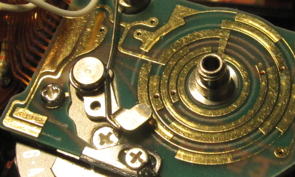
Canon A-1 Mode Switch Repair

My Canon A-1 (which I fixed the wheeze on here but please don’t use that method because it’s a bad hack that could cause more harm than good) was doing something weird. Every so often, when taking a photo indoors in aperture priority mode (Av), I would notice that the camera’s settings would jump to a really long exposure time like 30 seconds. Sometimes the only notice I’d get of this would be the camera actually taking a 30 second exposure instead of the more normal 1/60th at f/1.4 that I was hoping for.

The A-1 uses a single dial to select aperture settings in Av mode and shutter settings in Tv mode. The mode switch changes which part of the dial is displayed – the outer ring for shutter speeds, and the inner ring for apertures. At some point, I realised that the erroneous shutter speeds I was getting in Av mode were the shutter speeds at the same dial position in Tv mode. This was most noticeable when it was at the f/1.4 and 30 second position, but way less obvious when it was at the f/4 and 1/2 second position, because the difference between the expected and actual shutter speeds was smaller. I think this has been the cause of a few blurry photos. So I opened the camera to investigate.

The mode switch rotates around the shutter button, but it moves a sliding plate that has a crescent-shaped part that hides the unnecessary side of the dial, with a line half way along it to indicate the current setting. On the underside of one corner, this plate has a pair of brushes which bridge two contacts on the circuit board below when in Av mode and leave them open when in Tv mode. This plate is mounted on another plate which is only really fixed along the front side of the camera, the side opposite the brushes. This means that the contact of the brushes is slightly susceptible to flex due to finger pressure on the top of the camera, such as when finding and using the shutter button by touch, switching modes, or moving the dial.

Canon A-1 mode switch repair
Location of contacts, brushes, and crescent indicator on the sliding plate moved by the mode switch
Canon A-1 mode switch repair
Brushes from the underside. Note the two screw holes on the opposide side of the plate to the brushes.
Canon A-1 mode switch repair
The contacts bridged by the brushes. Note the tracks worn on the PCB from when the brushes slide back off the contacts when entering Tv mode.

I took the plate off and cleaned the circuit board contacts with some isopropyl alcohol. I also bent the brushes on the underside of the plate slightly downwards for a little extra spring pressure on the contacts, to hopefully reduce the effect of flex. Then I put it all back together. (Aside: my camera is missing a few washers from the shutter button and winder mechanisms, as well as the detent ball for the setting dial guard —  I think someone has been in here before me.)

So far, so good. I haven’t noticed the shutter speed bouncing around, and the test roll photos turned out fine.

Canon A-1 test
Canon A-1 test photo on Kodak UltraMax 400
Canon A-1 test
Canon A-1 test photo on Kodak UltraMax 400
Canon A-1 test
Canon A-1 test photo on Kodak UltraMax 400

Minolta X-9 Top Plate Removal and Reassembly

I posted these instructions over on Photrio, but thought I’d post them here as well.

In my last post, I replaced a dud capacitor on a Minolta X-9 that I was given by a friend. The Minolta X-9, otherwise known as the X-300s I believe, is similar to the X-300 and other X-series cameras, but not exactly the same. I couldn’t find specific instructions for working on this camera anywhere. Removing the bottom plate to fix the capacitor is easy, and the X-300 repair manual suffices for many other things, but the top plate is slightly different to the other X-series cameras, so I thought I’d figure out the way to remove it and put it here so others can use it. I mean, it’s really only points 1 and 2 that are different, but sometimes it helps to know things specifically. And I’m starting to think this camera is a bit underrated, once you come to terms with all the plastic.

Sorry for all the dirt in the photos, by the way.

Unless otherwise specified, all screws need a size J000 JIS screwdriver. All screws unscrew anticlockwise like normal.

Removal

1. Remove the finger plate around the shutter button. Prize this up from the front, gently, with a thin plastic tool. You can run this around the edges, but you get more purchase near the shutter button on both sides as there’s a locator pin further down. Just don’t apply too much pressure to the bit that goes around the shutter button because it’s thin.

Minolta X-9 / X-300s top plate removal

Minolta X-9 / X-300s top plate removal

2. There are two screws below the finger plate, marked in yellow. Undo these and you can remove the cover over the shutter speed selection dial and film advance lever screw. (The red arrow is the hole the locator pin goes into.)

Minolta X-9 / X-300s top plate removal

3. Remove the film advance lever screw (red arrow). This needs a size J1 screwdriver.

Minolta X-9 / X-300s top plate removal

4. When you take off the film advance lever, take care about the spring beneath it. This is tricky to get back in – it needs about a 270 degree anticlockwise rotation from its resting state to line up correctly, and you’ll probably need three hands. One end goes into the hole on the edge of the advance lever, the other goes into the hole marked in the second photo.

Minolta X-9 / X-300s top plate removal

Minolta X-9 / X-300s top plate removal

5. Undo the nut around the film advance axle with a spanner wrench.

Minolta X-9 / X-300s top plate removal

6. Take off the obvious top plate screws: two on either side of the viewfinder, one on the left end, and two on the name plate on the front.

Minolta X-9 / X-300s top plate removal

Minolta X-9 / X-300s top plate removal

Minolta X-9 / X-300s top plate removal

7. Take note of the position of your ISO selector and power switch. Undo the screw on the rewind knob. This needs a size J0 screwdriver, and you’ll need to brace the other end of the rewind axle with a cloth-covered screwdriver or similar. Lift off the rewind knob.

Minolta X-9 / X-300s top plate removal

8. Undo the plastic disk with a spanner wrench. This holds the ISO selector wheel in place. There is a circular wave spring below it. Lift off the ISO selector wheel

Minolta X-9 / X-300s top plate removal

Minolta X-9 / X-300s top plate removal

9. You can now take off the top plate. Don’t be too eager, because there are three wires leading to the hot shoe that are soldered on. Desolder them if you need to remove the top plate completely.

Minolta X-9 / X-300s top plate removal

So that’s the top plate removed.

Reassembly

A few pointers on lining things up when reassembling:

– The shutter button has a central pole that goes into a light grey tube near the shutter speed dial. The spring goes on first. There are three tabs around the edge of the button that prevent it from fitting through the top plate, so make sure you put this back before the top plate goes on.

Minolta X-9 / X-300s top plate removal

Minolta X-9 / X-300s top plate removal

– The viewfinder surround is only held in by the top plate screws on either side of it. There are two channels around its edge – the outermost is for attaching an eyecup or some such, and the innermost sits into the top plate. When sitting correctly in the top plate, the tabs with the screw holes fit between the top plate and the camera body. You might need some extra arms to keep this in place while also lining up the shutter button and power switch when you’re putting the top plate back on.

Minolta X-9 / X-300s top plate removal

Minolta X-9 / X-300s top plate removal

– The power switch actuator is the white lever near the rewind pole. The power switch interfaces with the U-shaped indentation at the end of the lever. (The ISO interface pole is behind the axle – just ignore that arrow.)

Minolta X-9 / X-300s top plate removal

– When the top plate is back on, but before you replace the ISO selector wheel, you can tell if the power switch is interfacing properly by viewing the switch through a hole in the top plate.

Switch set to Off: all white (lever is directly below the hole)

Minolta X-9 / X-300s top plate removal

Switch set to On: half white half empty (looking at the edge of the lever through the hole)

Minolta X-9 / X-300s top plate removal

– The ISO selector wheel has a hole on its underside that interfaces with the grey pole you can see at the far left of the two pictures above.

Minolta X-9 Capacitor Replacement

Last year I bought three enlargers from a family friend, who also threw in a bag of other camera stuff. This included a Nikon F4 and a Minolta X-9, neither of which worked properly. The F4 is my dream fix, but it’s a complicated beast. The X-9 (also called/very similar to the X-300S or X-370N) is a simpler machine by anyone’s estimation. Judging by resale prices, it’s considered outright basic. I am getting the impression, though, that it can easily outperform expectations as long as you can look past its gloriously 1980s plastic shell.

Minolta X-9 capacitor repair
The Minolta X-9 in question. The sorry-looking lens is a project for another day.

According to the internet, many of the later Minolta X series cameras are prone to a capacitor failure. An affected camera will appear to work until the shutter button is fully depressed, at which point the camera will power down; because the shutter never releases, the film advance lever can seem stuck. This Minolta X-9 displayed exactly this issue – the light meter would work on a half-press of the shutter button, but then the camera would die as soon as I pressed further.

I opened the bottom of the camera to have a look. Not without difficulty – I stripped the head of the screw nearest the capacitor in question. It was very stiff and I suspect it was slightly corroded by the residue from the burst capacitor, traces of which could be seen on the underside of the base plate. The plastic at the base of the capacitor, between the pins, was protruding further than it should, indicating that it had burst through the bottom and towards the screw.

Minolta X-9 capacitor repair
The old capacitor in place. It had burst out the bottom towards its pins, and you could see some residue nearby.

The most difficult part of this repair, for me, was learning to solder and desolder. This is a skill that I have come to learn is essential for repairing cameras – almost any camera made after 1970 seems to have parts that can only be removed after certain wires are desoldered (even the Voigtländer Bessamatic, which is a chaotic mechanical masterpiece). Thankfully, there is an electronics retailer in Australia that still provides an abundance of educational materials and affordable supplies for learning to solder. I learned the basics by making a small device with two flashing LEDs. This was a bit challenging, as I had decided to use lead-free solder for safety reasons, and my soldering iron tip was old and corroded; things got easier when I replaced the tip, and I was able to complete the device. Then I tried to unsolder it, found this difficult and gave up, and put it back together. As it still worked, I figured this was a good enough start…

Heady with my success, I dived straight into replacing the capacitor on the Minolta X-9. The old capacitor came off easily enough, so I trimmed and bent the pins of the new capacitor (took a while to find replacements with the same specifications and dimensions, but it is possible) and forged ahead. It’s a bit tricky to get the right alignment, since there’s not much support for the capacitor and you’re soldering it to a flexible circuit. I screwed up the alignment at first and had to re-solder it, and given the higher melting point of lead-free solder I was pretty afraid that I’d cooked something. Doubly so, when I put some batteries into the camera and nothing worked at all.

Minolta X-9 capacitor repair
The new capacitor soldered in. Those huge globs of solder are proof that I had only learned to solder recently and opted for the “overkill” approach.

I checked continuity between the capacitor pins and the next components on the flex circuit, and that was all fine. I measured voltage at the flex circuit and it checked out at around 3V, as it should have. But the camera wouldn’t even turn on. I was certain I’d killed it. And it’s not even a nice-looking paperweight.

When nothing works, go back to basics.

To test the camera, I had been using batteries straight out of my Minolta XE-5. These batteries were powering that camera’s light meter just fine, and they were measuring in at the correct voltage, so I assumed they were ok. But then, just in case, I put in a fresh pair of batteries. I pressed the shutter button. It fired. I pushed the film advance lever. It moved. I did it again. And again. And again.

Now, I know this is a basic camera, a manual focus SLR released at the time Minolta was well into its autofocus phase. It has only two or three more functions than the XE-5, which is about 15 years older. And it looks very much like an SLR and Darth Vader’s suit were spliced in a teleporter incident. However, it’s the first camera that I have resurrected from a state of complete malfunction. I’m pretty pleased with that. And in the process, I’ve seen some indications that the functions it does have are well implemented. When I ran a test roll of film through, it was comfortably familiar to shoot with, and it was plastic enough that I didn’t feel compelled to treat it like porcelain, so I quite enjoyed the experience. I might post a review up here sometime.